ARC-5 receiver power supply, an in depth look.
The power supply is essentially a vibrator power supply, but with an IC and mosfet instead of the mechanichal vibrator used in the old days.
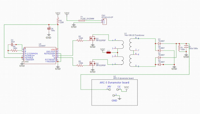
The schematic can be seen below:
It´s actually quite straight forward:
The CD4047 is operated as an astable multivibrator, providing two , out of ohase, square waves, driving the gates of the FET´s. The FET´s ground one end of the transformer winding, causing current flow, and induces voltage to the secondary winding (which in this case in the old primary) Switching frequency is determined by capacitor C3 and resistor R4. These values in the schematic gives approx. 50Hz switching frequency.
Optional 28V operation:I included holes on the board to hold a zener diode at the input of the CD4047 (max vcc 18v) in case 28v operation would be used (non-modified filament strings).
A different transformer is also needed. There is a transformer that fits the board, 14A-10R-36, by the number we can tell that it´s a centertapped 36v secondary, which gives us about 18v on each side of the center tap, which I feel is a bit too low. A voltage dropping resistor of suitable value instead of the choke going into the centertap would probably be needed, or else the voltage and current will likely be too high.
The FET´s can be any "convenient" N-channel FET. I happen to have a bucket full of IRFP450´s, so I used a pair of those. I have included holes for both TO220 and TO247 packages on the pcb.
Cooling the FET´s does not seem to be needed. After one hour at high volume, they are cool to the touch.
538-39700-0102 Molex spring terminal block 1pc
Other things needed I already had in the junkbox:
120R resistors 3pc
180K resistor 1pc
100K resistor (1W minimum) 1pc
20nf capacitor (actually 2 10nf i paralell)
100uf 25v capacitor at 4047 vcc rail, 1pc
1N4007 diodes 4pc
5x20mm fuse holder 1pc
IRFP450 2pc (´520´s will likely work good as well)
M3x6 brass nut 3pc
optional center tap choke. see text.
misc wires.
These pictures show the spacing to the rubber mount "cups". One one of my receivers with bad rubber mounts, the pins of the transformers was actually touching the metal. had to trim the pins back as much as possible to gain clearance.
Get those command receiver on air!!
Have a few boards available, shoot me an email in case you are interested.
//Tommy, SA2CLC


Can you send the files for the pcb?
ReplyDeleteI’m interested in a couple boards to get my. Receivers on the air. Please contact me. 73, NO2V
ReplyDelete