813 grounded grid linear amplifier
2 x 813 grounded grid linear amplifier
This year marks 10 years since I built this amplifier, and it´s been in use on almost all QSO´s I´ve had since then.
When I got into amateur radio back in 2013/2014, I quite soon understood that I needed a vacuum tube amplifier. SB220´s and L4B´s were high on the wanted list, but there wasn´t anything for sale at that moment. I stumbled across a pair of 813´s and sockets, and that´s what set the wheels rolling.
I begun by collecting the needed parts. High voltage transformer, variable caps, meters and such, and after that, it´s mostly a job of shaping metal and drilling holes.
An aluminum chassis was bent using the sheet metal brake at work. Reinforcement extrusions was bolted to the underside of the chassis where the HV transformer would go. With a finished box a rough layout was determined, and the hole drilling excercise begun.
After some trial and error, I actually got the thing to work. Had to iron out some stability issues. Still, to this day, I´m not quite sure what caused the amp to oscillate in the early phases of testing. Ended up using copper foil, connecting the grids and the tank circuit capacitors firmly together. That together with moving the tank coil seemed to cure the instability issue.
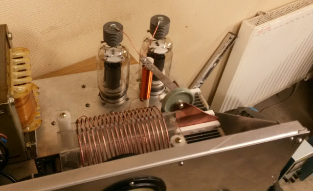
First RF made. February 2015. Note tank coil that was replaced
High voltage power supply
I'm using a 1 KVA (ccs), 1000V transfomer, together with a voltage doubler rectifier. This gives an unloaded voltage of around 2700V, and a, loaded to 500mA, voltage of about 2300.
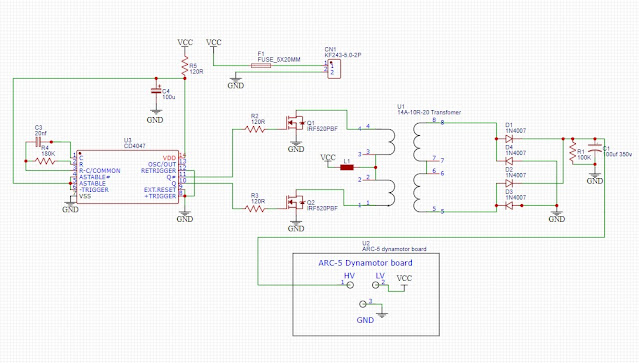
Homebaked fresh voltage doubler rectifier anyone?
Filament transformer
The 813´s have directly heated cathodes, the filament is the cathode. It means that these tubes does not need any warmup time, like indirectly heated cathodes, It also means that we need a centertapped transformer, to provide a path for the current through the tube. Transformers of this kind is not very common today, so I bought a transformer kit, with a pre wound primary, and wound the 10V centertapped secondary myself. It was quite fun to do, but a bit of a pain to get the voltage right at the tube sockets. I had to add a couple of turns to the transformer when everything was installed. A simpler approach would have been a small variac feeding the primary.
Tuned input
A tuned input circuit was needed. I tried a few variants of L-matches, which did work, but was would be a hassle to switch between so I got lazy, and installed an LDG Z-100 autotuner to tune the cathodes of the tubes. Works great.
Bias
This amplifier has a 50Kohm resistor as a cut-off resistor in the cathode lead, that gets shorted by a relay when keyed. I initially had a 5.1v Zener diode in the cathode lead to help lift the cathode potential above that of grids, to reduce idle current, but during tests, I found that to be unnecessary.
Looking at recommendations at idling current for AB class (amp keyed, no signal applied) values varied from 20-25mA per tube, to 70mA for the pair at around 2500v on the plates.
I could not get more than 60 no matter what. I even bypassed the filament choke to reduce the series resistance, to try to get more idling current. I figured the only way to get more idling current was to increase plate voltage, or stepping away from GG operation, adding a regulated G2 supply and negative G1 bias supply. That way setting the idling current to whatever would be possible, but that's no longer simple.
I figured, since the idling current was not excessive, and it was in the ballpark, between 50 and 70 mA, I just simply removed the zener.
Bias switch pcb with zener mounted on an isolated heatsink. Heatsink and zener was later removed
Tank circuit
I use a classical PI network, with an added L that goes between the coupling capacitor and the plates of the tubes. This serves to cancel out some of the high plate C that the 813's has, to improve efficiency on higher bands.
I added a cam to the bandswitch shaft, that operates a microswitch, which controls vacuum relays that switch in and out padding capacitors on the low bands. A two deck switch would have been way easier to use though.
The tank coil is two coils in series. The first few coil turns of the high band coil is made up of copper brake line, 1/4", then the remaining turns are 3/16 tubing. The second coil is wound on a ceramic former.
Initially, back in 2015, a few different coils were tried, and initially, I settled for 80-40-20 meters coverage. What you see here is the setup today.
160-10m coverage, with good output power on all bands, around 900W except 12 meters, which maxes out att around 500W, with low efficiency. On 10meters, I get 750-800W, with an efficiency of around 56%, which is pushing the 813's above their dissipation limit, but keep away from FT8, and it should be fine for many years still.
I use russian surplus B1B vacuum relays to switch in and out 160/80 padding caps and part of the tank coil on 160 meters.
Metering
I measure plate volts, cathode current and grid currents. I write grid currents, because I'm measuring the combined grid and screen currents. When tuning up, I'm keeping the grid currents below 90mA.
.jpg)


Comments
Post a Comment