Getting stuff done, Tram Titan 2

I have a few of them (!), and I also have the nasty habit, whilst I'm up at good momentum at an ongoing project, to get sidetracked by something else. I have fixed a few (or perhaps golden screwdriver-ered them) 11m tube radios and cybernet board "export cb's" for a friend of mine. It's fun, good practice and he enjoys using them.
However, Jan brought by a beautiful old Tram Titan 2 more than a year ago, for me to fix, and to add channel 24 (in Sweden, channel 24 is the go-to call channel for SSB). Easy enough I thought, a recap and a dds generator to replace a crystal. Turns out, I was in for more.
This project became a multi stage rocket, due to the projects needed finishing, so that I could finish this.
First off, the utracer needed to be finished, so that I could test the tubes in the radio, to know if there was any that needed replacing.
My variac needed some work and an outlet socket installed.
I needed to get the screen regulator on my big linear done, because that had been haunting me for too long.
I got sidetracked with a power meter and directional coupler, a linear amplifier, a big pile of tubes to test, a tube audio amplifier (although just in planning stage), a try to 4m convert an old ericsson two-way, and general reorganizing in the shack.
I guess I could work on focus.....
Anyway, now, the Tram should move along.

Recapped. Electrolytics have been changed.
I have inspected resistors, ceramic caps etc., I did a sneak-up with the variac, and noted that there was basically no receive, and no tx. The mic was missing, and the Tram was equipped with a strange mic socket. Looked around Ebay in search of a plug, but ended up changing it for a 4-pin socket instead.
The power socket was replaced with an IEC socket, with added ground.
A bunch of tubes was replaced, due to them testing low. Replacement of the 6BR8 brought the receiver to life.
Channel discs was cleaned up from old tape marking, lightbulbs was replaced.
Crystals
The Tram Titan 2 uses crystals oscillating at half the transmit frequency.
The receiver is a freestanding unit, with very few elements shared with the transmitter except the audio stage. The receiver is vfo controlled, with a crystal controlled IF.
My work on getting to channel 24 was initially an easy thing to do but I kinda screwed up and made it harder than it needed to be.
Note to self. Just because you can, doesn't mean you should. KISS.
I should have settled for giving up, say channel one, and retuned the receiver a little bit. The SI5351 board would just sit and oscillate at 27.235/2, feeding no1 crystal socket.
I made a board which holds the Arduino, SI5351A, two buffer amps, and full wave rectifier with a 5 V regulator. I added 3 voltage dividers, to read 24 inputs (channel switch) to be able to generate all the needed channels, and skip the crystals altogether. Empowered by the success of my CE20A vfo, I figured that wouldn't be a problem.
Skip forward to delivery from JLCpcb, to populating the PCB, and writing code. It all came together as expected. I could distinguish between 24 different switch positions, I could generate both RF drive for channel crystals, and also IF. My plan was (is) to generate the IF on the dds board, so that I can change IF if neccesary.

Issues
The issues started with a bricked arduino. If you switch power on and off quickly on an arduino, you could get it into a state where it is impossible to upload software to it. That happened to me due to a slipping test lead supplying power. Minimize the use of test leads. I borrowed another arduino from another project and continued. Could not get the transmitter on frequency. Turned out the SI5351 was dead. From what I do not know, possibly a transient on the +ve line.
Ordered a pack of 5 nanos, and 5 SI5351A boards off aliexpress.
Programmed the Arduino, and soldered in a new SI5351A. I was not able to communicate with that unit. Put together a new one on breadboard, to make sure it was okay, and with a test sketch generating 10 an 150 MHz, I installed everything on the board and supplied power. This time, the magic smoke escaped from the arduino. I checked wiring. I checked for shorts. I checked for anything obvious that could cause it, but found none. I started to think about the test sketch generating 150 MHz, feeding the buffer amp might be the cause. I had a strange arduino-fry behaviour years ago when building a 2M APRS tracker. Whenever it would go into transmit, the arduino cooked. Turned out to be the adjustable lab supply I was using, that lost it, when close to ~2M frequencies. Guess what. I'm still using it. I think and hope that was the cause the arduino failed, overvoltage.
Moving forward
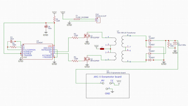
I'm installing a small transformer to steal some of the filament energy, to rectify and use to power the board. Like on the CE20A, one side of the filament is grounded, which makes getting more than 4v hard. The transformer chosen is a dual secondary on which the filament will be driving one low voltage winding, and the DDS board will rectify the other low voltage winding. The primary will not be used.
Test QSO
Aligning the transmitter was pretty straight forward following the manual, tweaking the interstage transformers and pi filter. There is really nothing to this transmitter. As simple as could be.
Got probably close to 4W output, which corresponds to what the manual says. Had a qso with Jan, but by using a separate receiver- the receiver is still not working properly.
More to come!


Comments
Post a Comment