A QRO tandem match for the amplifier build
A directional coupler for the amplifier.
In this post we take a look at the directional coupler I built for the amplifier. I wanted a built-in coupler to measure power and have SWR protection.
I built a tandem match coupler. Why, you might ask? Because I’ve built one before with good results, and after struggling with a Bruene coupler design(which I could never get to work properly), I decided to stick with what I know works.
 |
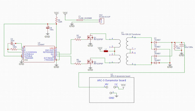
| Schematic representation of a tandem match. The transformers are wound on ferrite toroids where the primary is one pass of coax thru the center. Note that the turns ratio needs to be the same for the transformers, even though the cores may differ. |
Theory in brief (with disclaimer)
Expect no in-depth math here. This is a simplified explanation and more of a picture series on how I built mine, along with some thoughts on how to improve it.
A tandem match coupler works by sampling both current and voltage in the transmission line using transformers:
-
The current transformer sits around the feedline, where the coax itself is the one-turn primary.
-
The voltage transformer has its secondary connected across the feedline and samples the line voltage.
Because forward and reverse travelling waves have different voltage/current phase relationships, you can form two linear combinations:
-
Forward port = current + voltage/Z₀
-
Reflected port = current – voltage/Z₀
One combination reinforces the forward wave while canceling the reverse, and the other does the opposite. That’s how the coupler “knows” which power is forward and which is reflected.
Core choice and winding
I used –61 material, Larry Phipps (Telepost, LP-100) recommends it and has proven it works well.
-
Voltage transformer: two FT-140-61 cores taped together with Kapton, wound with 27 turns using a Fusion 360-made winding template (basically a strip marked with 27 bars covering ~60% of the circumference).
-
Current transformer: one FT-140-61 with the same number of windings as the voltage transformer.
For the thru-line I used RG-393 (silver-plated copper with Teflon dielectric, great for soldering). For the secondary leads (forward/reflected) I used RG-400.
Be sure to ground only one side of the coax braid. This acts as an electrostatic screen, and if both sides of the braid is grounded, the transformer won't work properly. To my understanding, it does not matter which side is grounded, but I cannot confirm this since I have not tested it A/B a with measurments.
The cores are mounted on 3D-printed plugs that fit snugly onto the coax.
You may also notice that in many tandem match couplers, the voltage transformer core is larger than the current transformer core. The reason is that it has to withstand the full RF line voltage and must present a high impedance at the lowest operating frequency. If not, it risks saturating or effectively shorting the signal. I ran some tests on some small, ready made boards available from Aliexpress and Ebay, and found that their rating is just below 20W for a 1:1 load before the voltage transformer started heating up rapidly. Higher SWR would lead to a higher voltage and reduce the power handling capability even more. Since I had many cores (pack of 10 at good price from Ebay) I decided to go with lots of headroom, and stacked 2 cores for the voltage transformer.
Even though the cores can differ in size or be stacked, the number of turns has to be identical on both transformers. Otherwise the coupling factors will not match, and forward/reflected cancellation will be skewed.
Mechanical layout
The enclosure is a cheap “Hammond-style” diecast box from Temu, roughly like a Hammond 1590C. I bought a handful since they’re handy for RF projects.
Inside, I added a dividing wall from aluminum scrap to keep things separated and reduce stray coupling. Feedthrough bushings were turned on the lathe from teflon for the interconnecting wires between the transfomers.
This is probably where I could improve the most, but honestly, I don´t know where to start. Looking at the LP-100 coupler, we can see that on the voltage transfomer, there is no "feedthru" coax at the sense ports. It uses a piece of aluminum rod, with one end bolted to the enclosure and with the top end connected to forward voltage. I think it would be beneficial to mount the voltage transformer at right angle from the current transfomer, but that theory might not hold. A QEX article describes a coupler with a diagonal dividing wall and twisted wires. Experimenting is encouraged.
 |
| A pile of goodies to start the project. RG393, FT140-61, N connectors and 1590C sized boxes |
 |
| Prepping coax. Teflon coax is a joy to work on. No worries to melt the dielectric |
 |
| Dividing plate. I glued the angles to the plate while holding it in place. Later I drilled holes and bolted it together. |
 |
| Test fit of current transformer |
 |
| Winding template. 27 bars laid out on the diameter. Very helpful in getting a neat winding layout |
 |
| Testing! |
Directivity and coupling factor
I have an older digital wattmeter, with remote coupler, which reads almost 150 W on 160 m for a real 100 W input, while on 10 m the same 100 W barely shows 70 W. Without per-band calibration, that’s useless.
The more I have learnt when building this, The more I want a coupler with good directivity. Why? A varying coupling across HF can be solved with a smart controller, with frequency counter input and per-band calibration to get "correct indicated power". However, if the directivity is poor, the measurment error can be all over the place.
Anyway. I measured the coupler and it was better than the old unit
-
Coupling ≈ –32 dB across the HF range.
At first, directivity was only about 18 dB, which was disappointing. A textbook correct tandem match should be reversible, meaning I should be able to swap ports, and reverse the bridge with the same coupling and directivity. This was not the case and I noticed it behaved better in one direction. You can add a trimmer capactitor to one of the sense ports to cancel out some of the winding capacitance which I tried. I first installed it on the REF port, but it did not improve things. Out of curiosity I flipped the bridge and moved the trimmer to the FOR (now REF) side instead — and suddenly things started moving. With some careful adjustment I was able to tune out the stray capacitance, and directivity jumped to about 28 dB at 30 MHz. The numbers improve further as you go lower in frequency.
 |
| 60 pF compensation capacitor installed. |
How much directivity do we really need?
In simple terms, directivity tells us how good the coupler is at separating the forward signal from leaking into the reverse port and vice versa. Directivity sets the lower limit for how accurately SWR can be measured. With a ~28 dB coupler, a true SWR of 1.22:1 might appear anywhere between about 1.13:1 and 1.33:1, depending on phase. That’s accurate enough to tell you whether the match is good, but not precise enough to split hairs between 1.05:1 and 1.08:1. ( Which, in my opinion is like comparing Bud Light vs Miller Lite. At this point you’re arguing about water content and label design.)
If you’re considering a commercial high-power wideband coupler, pricing starts at around $1000, and even then you’ll hardly see better than about 30 dB directivity across HF. To go further — for example, to reliably resolve differences down in the 1.05:1 range — you’d need something on the order of 40 dB directivity, which is only found in narrowband, lab-grade devices.
The takeaway: 28–30 dB is already very good for an HF broadband coupler, and more than adequate for QRO power monitoring and SWR measurement in the amateur shack.

Load resistors and terminations
For the sampling loads inside the coupler, I used two 100 Ω non-inductive resistors in parallel, giving 50 Ω. They are in a TO-220 thick-film package, non-inductive, and available from many suppliers such as Mouser. Using non-inductive types is essential, otherwise the frequency response becomes skewed.
It’s also worth pointing out that the terminations used during testing play a big role in the measured directivity. Many 50 Ω loads are themselves only good for about 25–30 dB return loss (roughly 1.05:1 SWR). That already limits how much directivity you can verify in practice.
With the coupler tuned to about 28 dB directivity, that corresponds to SWR accuracy down to roughly 1.5:1 with decent confidence. In practice that’s more than good enough for amplifier monitoring — but it also explains why chasing tiny differences (like 1.05:1 vs 1.08:1) is meaningless without very high-grade loads and lab equipment.
Conclusion
Overall, I’m very happy with this coupler. The coupling is flat across the HF range, directivity is 28 dB at 30 MHz (and better at the low bands), and mechanically it feels solid. I have no doubt it will handle the full power and some more from the amplifier.


Comments
Post a Comment